How to Choose and integrate a medical device with stepper motor

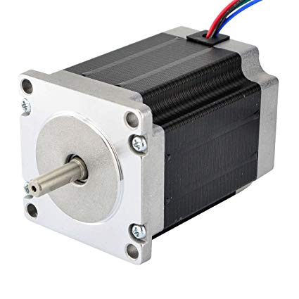
Recently almost every medical device I design requires a stepper motor. After working with these motors so frequently, I’d like to share what I’ve learned about medical device stepper motors, the different types of stepper motor configurations, and how to drive stepper motors properly.

How to Choose and integrate a medical device with stepper motor

Stepper Motor Drive Configurations
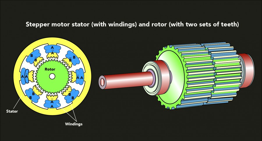
Stepper motors typically come in two motor winding configurations. Before selecting which configuration is appropriate for your application, you should understand the basic difference between the two. This choice will be important when selecting how to drive the motor.

Pro Tip: You can use a unipolar motor as a bipolar motor if you ignore the center tap. This can come in handy if a particular design of motor is only available in a unipolar configuration.

How to Choose and integrate a medical device with stepper motor

Stepper Motor Drive Signals

Typically three types of drive signals are used to control the motion of a stepper motor. Each drive type increases in complexity, but adds additional features and options.

How to Choose and integrate a medical device with stepper motor

A wave drive only energizes one phase at a time. Wave drives are simple to implement with basic hardware, but are rarely used. Because only one coil is energized at a time, torque is significantly reduced.

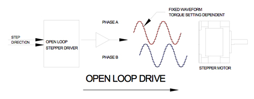
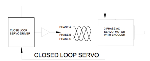
Stepper Motor Drive Circuits
The most common methods for driving a stepper motor include a simple constant voltage or L/R (L refers to electrical inductance and R stands for electrical resistance) driver, a chopper drive, or a sine wave/micro-stepper driver.

Stepper Motor Integrated Drivers
Once a stepper motor hybrid has been selected to suit its mechanical requirements, the next thing is to get that motor turning. It is easier than ever to make a motor operational by selecting an off the shelf stepper motor driver IC or development board. Many of these boards provide features such as current feedback, built in acceleration profiles, and even onboard path planning for more complicated motion control.

Source:https://blog.oyostepper.com/2019/12/21/how-to-choose-and-integrate-a-medical-device-with-stepper-motor/

The Denifition of hybrid stepping motors?

Hybrid stepper motors combine aspects of both permanent magnet (PM) and variable reluctance (VR) stepper motors. Like PM motors, they contain a permanent magnet in the rotor teeth. Two sets of teeth called cups ring the rotor. One ring is all south poles, and the other ring is all north poles.

FAQ3

Like VR motors, hybrid stepper motors have stator poles. Note that stator poles in hybrid motors are sometimes called teeth. (For more information)

To illustrate how these motors work, consider a 1.8° hybrid stepper. The teeth of one ring are offset from those on the other ring by 3.6°. The stator poles are offset by 90° and these are opposite polarity, so that every 180° the stator poles are in identical polarity. The rotor poles exist in sets of four, with two being north poles and two being south poles. The rotor poles align alternately with the rotor’s teeth and cups, so that one set of rotor poles attracts fully while the other attracts and repels ¾, ½ or ¼ of a tooth. If there are 50 teeth, the pitch angle is 7.2° … so at the next step, the motor rotates to the next closest step, which is 7.2° × ¼ = 1.8°.

When the current changes, the rotor can turn a very small amount—an improvement over basic PM motors and VR motors. Newer control techniques such as half-stepping and microstepping let designers get even finer movements of rotation, which make for more exact output than that from VR stepper motors (which can’t usually be microstepped). nema 17 Hybrid stepper motors also have higher torque-to-size ratios and higher output speeds than other stepper-motor types. They are also quieter than VR stepper motors.

How to Convert open loop to closed loop stepper control

Hi,

I have a project that uses a 13Nm Open Loop stepper motor (4 wire / 2 phase, 48VDC @ 5A per phase) to move a belt type linear axis … control of the stepper drive is via 5V pulse/direction I/O from a custom microprocessor.

Initially it worked well but under certain conditions the motor looses steps which causes a gradual positional error on the linear axis. as such I am considering modifying the setup to closed loop motor control by adding a Omron 1000 P/R Incremental quadrature encoder, the Granite Devices web site states that the Ioni drive (with X1 mother board) can control stepper motors and supports rotary encoders.

An alternative might be to use a a linear encoder for position feedback but i have no experience in using them …

I need it to automatically recover from a lost step/s situation by using the feedback device …

I’ve been considering using a hybrid stepper driver from china but the software is bound to be flakey with no support and it only supports 2 ph steppers where as spending the extra on a Ioni drive would ensure that the drive would be future proof if i wanted to switch to a servo motor at some point in the future and of course the Granity software is far superior and would allow me to tune the motor to the application.

Just wondering if anyone here has any experience in using a stepper in closed loop control ? … any advice or help would be most welcome …

Cheers
Oscar

Why do we combine a servo motor with a gearbox

Do you know why we still use today gearboxes while servo motors becoming stronger and more advanced? The gearboxes of Apex Dynamics are used in many cases in combination with a servo motor, for example because they have low backlash and are able to deal with high torque. But still we did not give an answer to the previous question: why! In this article we discuss the operation of a servo drive and translate this through to the gearboxes.

Why do we combine a servo motor with a gearbox
What is a servo-drive?
The prefix servo comes from the Latin servus which means slave or servant. Technically translated tis means to follow or execute a command. A servo motor follows the (complex) task given to him.

For industrial applications, servo motors are used where a drive-system has to be accurate or highly dynamic. The feedback to the motor is done through a resolver (analogue sensor of rotation) or encoder (digital sensor of rotation). A servo motor is controlled by a servo amplifier, possibly with a shaft controller.

The rotation frequency of the actuator is given back by the resolver or encoder. This is capable in addition to the rotational speed, also to determine the position of the rotor and the direction of rotation. The servo amplifier compares the set rotational frequency with the measured rotational frequency. Now the servo amplifier can drive the actuator to the desired values.

See more:https://www.oyostepper.com/

How Feedback Encoder of Step Motor Operate

Feedback is used in closed loop Motor systems in applications all over the world to control speed and/or position, and it has an important role in keeping equipment operating smoothly and accurately. Feedback is available in a variety of devices as well as models. It is important to understand how feedback operates, so the best benefits can be used in the application.
OPEN LOOP VS CLOSED LOOP
Many applications operate open loop and many operate closed loop. In an open loop system, the operation can become uncontrolled; in a closed loop system the process is controlled. The difference is feedback.

52

An open loop system is a process in which the signal travels from the control to the motor. An example of an open loop system is as follows: a motor is used in a bin sorting application, and everything proceeds as expected as long as the motor can pick and place parts in the proper bin. However if for some reason the mechanism jams and the motor can’t move, the control is not aware of the situation and will continue sending commands that are essentially ignored, so the parts do not get sorted.

In a closed loop Stepper system the signal travels from the control to the motor, as above, however the difference is that there is another signal, a feedback signal, which returns to the control, thus informing the control the operation was successfully. If the feedback informs the control that the operation was not successful, then the control could alert an operator that the process was not completed correctly. Closed loop systems use feedback for speed/position information and process control in many applications.

There are a variety of devices available in the marketplaces which are employed to derived information about the application’s speed and/or position thus controlling and guaranteeing that the process occurs correctly. These include: tachometer, Hall sensors, encoder, and resolver.

Click the button below to read the complete guide, and view a basic chart on various feedback devices and their advantages and various characteristics.


Some Difference Between Servo and Stepping Motors

Servos and Steppers are the names of two different device types used to control motors. From a distance, both device types can appear similar, as they both allow a user to control speed, position, and torque. However, the control methods, capabilities, and prices of each type differ enough that it becomes important to understand, even from a high level, so a system can be properly sized, both for performance and for the cost. Below are the three main differences, as well as an introductory overview of those differences, to help you choose the best method of control:

Some Difference Between Servo and Stepping Motors

1.Position. Steppers are an Open Loop system, meaning that they simply move incremental pulses. A stepper motor has more poles (Poles are the North and South Magnetic Windings of a motor, that are a natural stopping point for the motor shaft) than a servo, typically between 50 and 100. A single step pulse is the movement from one pole to the next.

2.Torque and Speed. Stepper motors are limited to around 2000rpm, and about 1HP. A servo is able to achieve speeds many times that, and control much larger motors. Since the Stepper motor has more poles, at higher speeds the stepper’s torque will be degraded.

3.Price. Stepper systems are a fairly simple way to integrate motion control. The hardware requirements are relatively low cost, and they are easy to setup and maintain.A servo has a much higher hardware cost and requires additional components, such as communication modules, specific controllers, and additional feedback cabling. A typically forgotten cost is the additional time required to properly setup, configure, and then tune for optimal performance.

The schematic of stepper driver and power circuit

How to Prevent Step Loss for stepping motor

The use of stepper motors for cnc is an excellent choice. However, a key concern is step losses. Step losses can be prevented or corrected in most instances. prevent step loss in stepper motors

Stepper motors operate open loop. When a stepping motor does not operate correctly in a specific situation, the common conclusion is that either the drive electronics or the motor is faulty. The motor selection and the choice of the driver are critical. However, other factors contribute to step losses.

The following points are important to examine for the analysis of step losses or non-operation in a methodical fashion across a variety of applications:

Stepper Motor Selection
Motion profile
Start-Stop operation
Trapezoidal profile
External commutation errors
External events
Back driving
Increase of the pay load over time

Stepper Motor Selection
The first task is to select the right stepper motor for the application. For the best selection, those basic theoretical rules have to be respected:

Select the motor based on the highest torque/speed point required by the application (selection based on the worst case)
Use a 30% safety factor from the published torque vs. speed curve (pull-out curve).
Ensure that the application cannot be stalled by external events
It is important to remember that a stepper motor does not operate like a DC motor. There is no working point parameterization, and the phase current does not increase to overcome variations of load. As long as the speed vs. torque requirement of the application is within the specs of the motor, no problem will be encountered. If this requirement is out of the specs, the motor stalls (OK or NOT OK functionality). In any case, the current in the phases is not changing and adapting by itself to the situation.

To read the complete technical paper and learn more about how to prevent step losses and tips for troubleshooting, download the free 4-page pdf now by clicking the button below.

Source: https://www.oyostepper.com/article-1086-How-to-Prevent-Step-Loss.html

How to perfectly control a stepping motor

Full step control of step motors can only be achieved by completely turning on its winding. This kind of achievement of control is till now, one of the simplest, safe and economical way of guiding the step motors.

425_

Most of the available step motors, in the market, usually consist of four phases. Each of these phases has to be individually powered and made to turn on, to keep the stepping motors rotating. Although there are numerous methods through which this state can be achieved. But of them use of transistor, is the most common one to initiate and end the operation of these phases. So when the complete full step of these stepper motors takes place, the shaft of the 1.8 deg stepping motor mechanically rotates a mere 1.8 degrees. That’s why it takes approximately 200 steps of rotation to complete one full revolution.

Transistors don’t have a brain of their own. They can do only a specific kind of work, that too without any change in their work behavior or deviation. So to control the working of these transistors, micro-controllers are required. Initially these micro-controller used to be big, little bulky and heavy. But with advancement in micro-controller and micro-processor based technologies, much changes have taken place in the way they are being designed and developed. Currently available micro-controllers have reduced in size and they can be now much easily embedded in any kind of transistor.

Use of micro-controllers in stepping motors was initiated some 2 decades back. Although using those chips boosts the price of step motors. But their use in step motors makes them robust in nature and much flexible in use. A micro-controller controlled stepping motor can be used in many different conditions. More technological advancement in the way they are being developed is also improving the performance of stepping motors.

Drive methods for stepper motors

Stepper motors have 50 to 100 poles and are two-phase devices, where servo motors have between four and 12 poles and are three-phase devices. Stepper motor drives generate sine waves with a frequency that changes with speed … but with an amplitude that is constant.

Closed-Loop-1

Servo drives, on the other hand, produce sine waves with variable frequency and amplitude, allowing them to control both speed and torque.

Servo-Diagram-2

Control methods for stepper motors
Traditional stepper motors move when they receive a command to advance a certain number of pulses, which correlate to a distance. Steppers are considered open-loop systems because they lack a feedback mechanism to verify that the target position has been reached. Servo motors also move on receipt of a command signal from their controller. In contrast to the open-loop operation of stepper motor systems, servo motors are closed-loop systems, with built-in encoders that continuously communicate back to the controller, which makes any needed adjustments to ensure the target position is reached.

Closed-loop stepping motors online eliminate many of the disadvantages of traditional open-loop stepper systems, making them similar in performance to servo motors. But servo motors outperform even closed-loop steppers in applications that require high speed, high torque at high speed, or the ability to handle changing loads.

NEMA 42 Motor to Meet Your Special Applications

NEMA 42 stepper motor is the largest stepper motor of the stepper motor family. This is known to be the finest type of stepper motor. It has the unique features of both, permanent and variable reluctance motor. It is an electronically driven motor, and it is used in the robotics industry and many other industries. The stepper motor is mainly used in the applications where precise and efficient motion control is required whether the motion is linear or rotational. In case of rotational motion, when it receives digital pulses in an accurate sequence it allows the shaft of the stepper motor to rotate in discrete step increments.

nema 42 stepper MOTOR


Industrial Applications of NEMA 42 Stepper Motor:

Robotics Industry:

Nema 42 110 x 110mm motor is widely used in the field of robotics as it provides high torque and has the quality to work for precise control. Nowadays as the world is getting dependable on the technology robotics industry has got a great chance to grow. The growing field of robotics is partially dependable of NEMA 42 stepper motor for their growth, as it is the best electrical motor to be used for the robotics applications.

CNC Industries:

CNC (Computer Numeric Control) industries are those who manufactures CNC equipment like CNC routers, CNC milling machine, and various other CNC products. These equipment are computer controlled devices that are used for cutting applications. These applications also require precise control and hence NEMA 42 Stepper motor is highly preferred electrical motors for CNC applications.

3-D Printing or Rapid Prototyping Industries:

3-D printers requires precise control and accuracy for their operation and hence these type of printers use NEMA 42 Stepper motors. These motor provide a high level of precision because of the direct relationship between the rotation angle and the input pulse. They can be paused, and the direction of rotation can be reversed with a great precision, making the NEMA 42 Stepper motor an excellent component to be used for rapid prototyping applications.